Hubbell 4 Way Switch Wiring Diagram
Wiring A 4 Way Switch
4 Way Switch Wiring Diagram
4 Way Switch Wiring Diagrams Do It Yourself Help Com

Diagram Hubbell Light Switch Wiring Diagram Full Version Hd Quality Wiring Diagram Diagramfinder Billysbones It
Https Encrypted Tbn0 Gstatic Com Images Q Tbn 3aand9gcr 2vyddzwxk Xaqidbgc4vlkgespcquiu Fa Usqp Cau
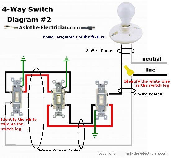
Diagram 3 Way Switch Schematicbo Wiring Diagram Full Version Hd Quality Wiring Diagram Livediagramm Caracozziexpert It
Add to project list.
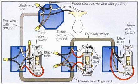
Hubbell 4 way switch wiring diagram. At the risk of being repetitious make sure the power is off before making any connections to an existing circuit. Same diagram but with 4 way switch added. The black line wire connects to the common terminal of the first 3 way switch. All you have to do is find the 3 wire running from one 3 way switch to the other 3 way switch and install the 4 way switch between the.
In fact a dimmer can be used this way in place of any of the 3 way switches on this page. 4 way dimmer switch wiring diagram. Bare or green ground wires are spliced together with a pigtail or two and then connected to the metal switch box with a 10 32 machine screw and to the green screw on the switch. Switches and lighting controls combination devices residential grade 2 single pole toggles 15a 120v ac self grounding side wired brown.
This 4 way switch diagram 2 shows the power source starting at the fixture. A 3 wire nm connects the traveler terminals of the first 3 way switch and the first 4 way switch. The white wire of the cable going to the switch is attached to the black line in the fixture box using a wirenut. How to wire a 4 way switch.
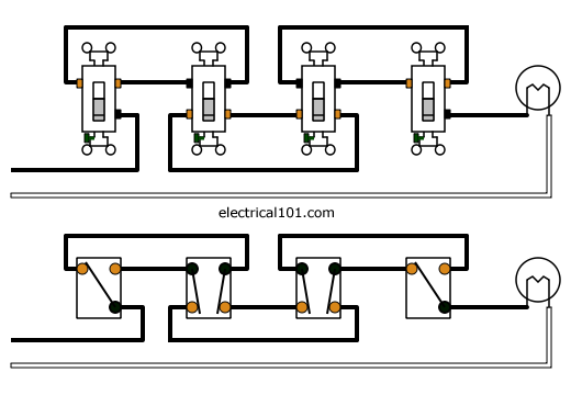
3 way and 4 way switch wiring diagrams. All switches in between will be a 4 way switch. To make this circuit work a 3 way dimmer can be used in place of one or both of the standard 3 way switches. By hubbell wiring device kellems.
Home decorating style 2020 for hubbell 4 way switch wiring diagram you can see hubbell 4 way switch wiring diagram and more pictures for home interior designing 2020 174816 at manuals library. First of all we need to go over a little basic terminology on switches. A 3 way dimmer has 4. Switches and lighting controls combination devices residential grade 2 single pole toggles 15a 120v ac.
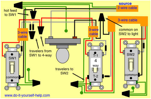
So let s say you have an existing three way circuit and you want to add another switch to it. This is the wiring for a dimmer in a 4 way circuit. Hubbell wiring device kellems offers basic electrical wiring diagrams and electrical design assistance for improved residential and commercial wirng design. Three wire cable runs between all the switches and 2 wire cable runs to the light.
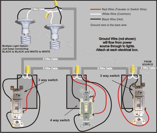
Typical 4 way switch wiring nm cable in the 1st diagram below a 2 wire nm cable supplies power from the panel to the first switch box. Even if you intend to have only three switch s or ten of them. 4 way switch wiring diagrams this 4 way switch diagram 1 shows the power source starting at the left 3 way switch. Wiring a 4 way switch is simply adding a switch to an already existing 3 way switch circuit.
Sometimes the switch wiring connection diagram is printed on the inside of the 4 way switch packaging box see example below.
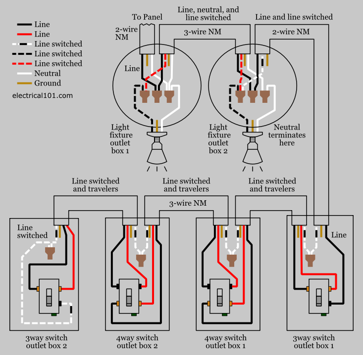
Diagram A 3 Way Switch Wiring Diagram For Hubbell Full Version Hd Quality For Hubbell Reddiagram Piola Libreria It

Diagram Hubbell 3 Way Switch Wiring Diagram Full Version Hd Quality Wiring Diagram Structuraldesignerjobs Artigianatosalento It

Installation Of Single Pole 3 Way 4 Way Switches Wiring Diagram Electrical Wiring Electrical Switch Wiring Electrical Switches

Wiring Diagram Fan Light Kit And 3 Way Switches Ceiling Fan With Light Light Switch Wiring Ceiling Fan Wiring

How To Wire A Four Pole Headphone Jack Di 2020

Hubbell Power Systems Products For Electric Utilities Telecommunications And Construction Industries Electrical Projects Electrical Grid Electricity

Disposal Wiring Diagram Home Electrical Wiring Diy Garbage Disposal Garbage Disposal Installation

Pdf Download

Nema Locking Configuration Chart Power Wire Chart Plugs

Https Encrypted Tbn0 Gstatic Com Images Q Tbn 3aand9gcstu Eb3q1fdrfwo Bqtczxhm9m6ta4olxq4g Usqp Cau

How To Wire Switches Wire Switch Outlet Wiring Electrical Switches

Awesome Metra 70 7550 Wiring Diagram In 2020 Metra Wire Instruction

Elegant 1990 Jeep Wrangler Wiring Diagram In 2020 Jeep Tj Jeep Jeep Wrangler
