Motion Sensor Light Switch Wiring Diagram

Zenith Motion Sensor Wiring Diagram Outside Lights To Motion Sensor Lights Handyman Wire Home Electrical Wiring Motion Sensor Lights Electrical Wiring

Image Result For Wiring A Motion Sensor Light Diagram 3 Way Switch Wiring Three Way Switch Light Switch Wiring
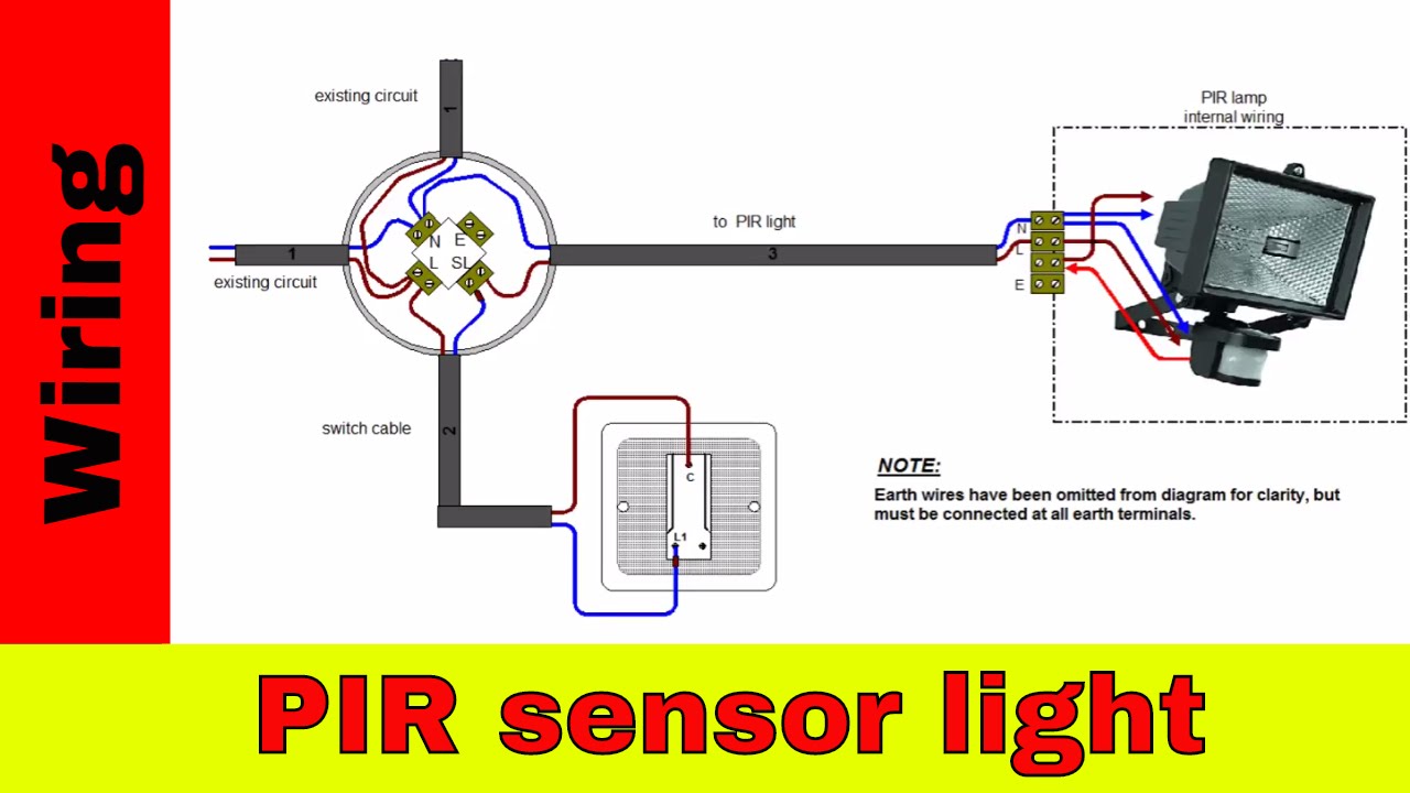
How To Wire Pir Sensor Light Youtube Light Switch Wiring Motion Sensor Lights Light Sensor

Motion Sensor Light Wiring Diagram Motion Sensor Lights Light Sensor Motion Sensor Lights Outdoor

Light Switch Wiring Diagram Australia Hpm Photoelectric Sensor To Outdoor Ceiling For Outside Mot Motion Sensor Lights Light Switch Wiring Photoelectric Sensor

Motion Sensor Light Wiring Diagram Elegant In 2020 Sensor Lights Outdoor Outdoor Flood Lights Outdoor Lighting Wire
A wiring diagram is a simplified conventional pictorial depiction of an electrical circuit.
Motion sensor light switch wiring diagram. 2020 11 12 motion sensor lights wiring diagram for wiring in series. Sometimes the wires will cross. Colours can also be used to differentiate cables. But it does not mean link between the wires.
As stated earlier the traces at a motion sensor wiring diagram represents wires. Variety of motion sensor light wiring diagram. It reveals the elements of the circuit as streamlined shapes and also the power and also signal connections between the tools. Home motion light switch light wiring diagram data wiring diagram motion sensor wiring diagram wiring diagram not 4 wire o2 sensor wiring diagram september 13 2018 april 12 2020 wiring diagram by anna r.
Motion sensor lights wiring diagram for wiring in series. For example if a module will be powered up and it sends out a new signal of fifty percent the voltage and the technician would not know this he d think he provides a challenge as he or she would expect a new 12v signal. There will be primary lines which are represented by l1 l2 l3 etc. Posted by erddiagram comdigitale fr on.
Motion sensor light switch wiring diagram effectively read a electrical wiring diagram one offers to find out how typically the components within the system operate. Injunction of two wires is usually indicated by black dot to the intersection of two lines.

Zenith Motion Sensor Wiring Diagram Is One Example Of A Occupancy Motion Sensor Switch Wiring Diagram Sensor Bath Exhaust Fan Diagram

White Motion Sensor Wiring Diagram Sample Motive Ideas Lighting Decoration Themes Adjustable Electronic Gif Resize D336 2c202 O Motion Detector Sensor Detector

Cooper Motion Light Wiring Diagram Wire Center Throughout God Security Light Wiring Diagram 8593 Security Lights Lights Motion Lights

Motion Sensor Light Switch In 2020 Light Sensor Motion Sensor Lights Light Sensor Circuit

3 Way Switch With Power Source Via The Light Switch How To Wire A Light Switch Electrical Switch Wiring Light Switch Wiring Three Way Switch

70 Beautiful Flood Light Wiring Diagram In 2020 Light Switch Wiring Motion Sensor Lights Light Sensor

How To Add Two Motion Sensors To Existing Light Circuit Motion Sensors Sensor Motion

Wiring Diagram For House Light Bookingritzcarlton Info Home Electrical Wiring Electrical Wiring Light Switch Wiring

3 Way Switch Wiring Diagram Home Electrical Wiring Diy Electrical 3 Way Switch Wiring

Zenith Motion Sensor Wiring Diagram Wiring In The Home Motion Sensor Security Lights Motion Sensor Security Lights Motion Sensor Lights Sensor

Pin On Wiring Diagrams Paint Colors Worksheets Cv Resume Images

Pir Motion Sensor Circuit For Human Detection And Lighting Electronic Circuit Projects Electrical Circuit Diagram Electronic Schematics

3 Way Switches For 3 Lights Wiring Diagram Light Switch Wiring 3 Way Switch Wiring Three Way Switch
